Soft robotics · Tactile sensing · Deep learning
Zero-Shot Deformation Reconstruction for Soft Robots
Estimating a soft robot’s changing shape from touch,
when a camera cannot see it.
Accepted to IEEE/RSJ IROS 2026 · Second author
How do we sense shape without a clear view?
Imagine a soft gripper reaching into a box. A camera outside may not see its tip, and a soft body does not have the fixed joints and links of a rigid robot. A sensor attached to the surface could help estimate how it bends and twists.
We studied the shape-estimation part of this problem: using a small flexible sensor array to drive a model of the whole object. We trained on a fabric platform and tested on two previously unseen pneumatic soft robots. The box scenario motivates the work; the experiments evaluate reconstruction, rather than closed-loop grasping.
My role
From sensor data to a trained model
Acquisition & experiments
Developed sensor recording and real-time readout visualization, co-designed the acquisition protocol, and collected tactile measurements and structured-light scans.
Data & model training
Organized the 100-channel datasets, co-developed region preprocessing, trained the deformation model, and refined the code with my collaborator.
Evaluation & communication
Evaluated reconstruction, prepared experimental figures and demonstrations, and contributed to the manuscript as second author.
The method
Small sensor, whole-object reconstruction
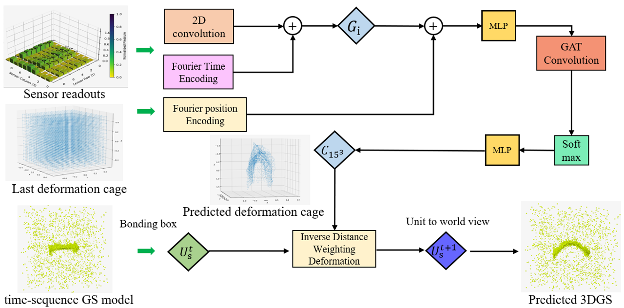
Instead of predicting every point independently, the network moves a control cage. Fixed geometric weights spread that motion to the object’s 3D Gaussian representation.
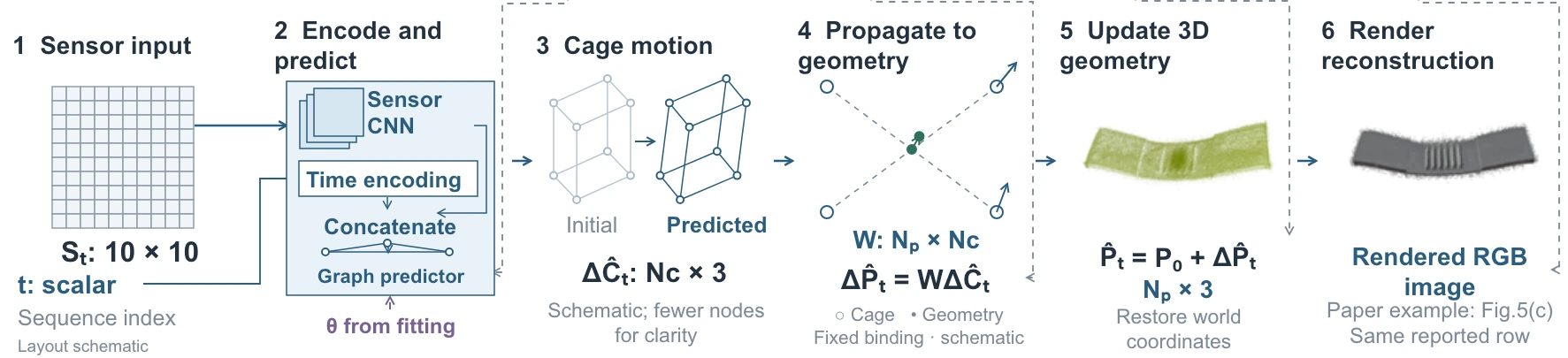
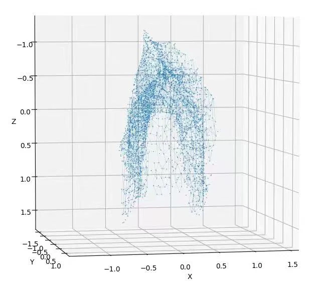
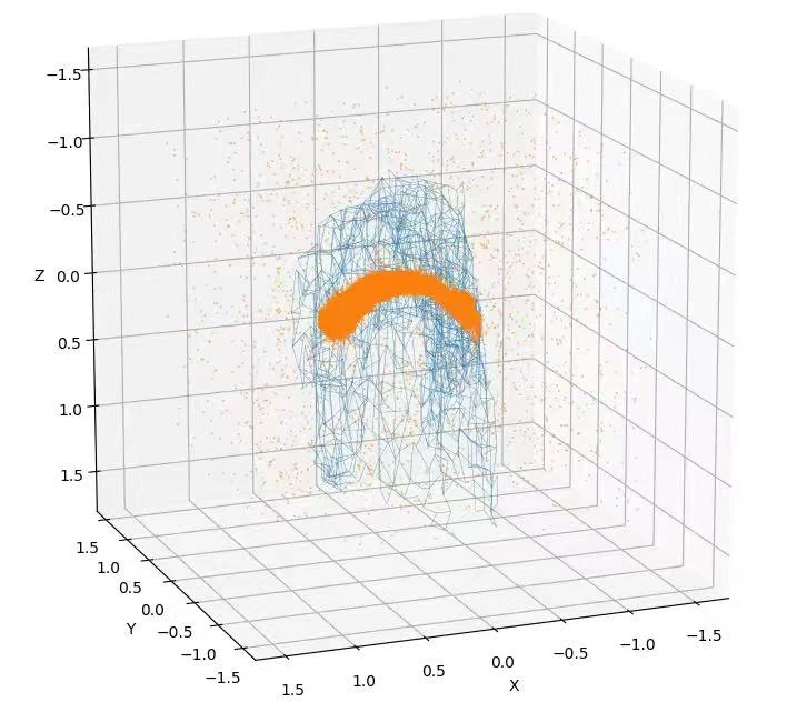
What “zero-shot” means here. The two test robots were not part of training. Each still needs an undeformed geometry model and sensor-region alignment; no robot-specific deformation dataset or retraining is used.
System implementation
Sensor array & readout
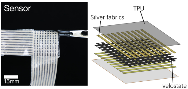
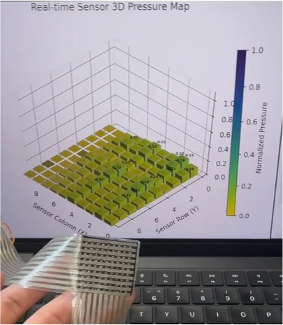
I developed the acquisition and visualization tools used to inspect the array’s response, record measurements, and prepare the data for training.
Learning from paired data
Supervised deformation learning
Preparing geometric references
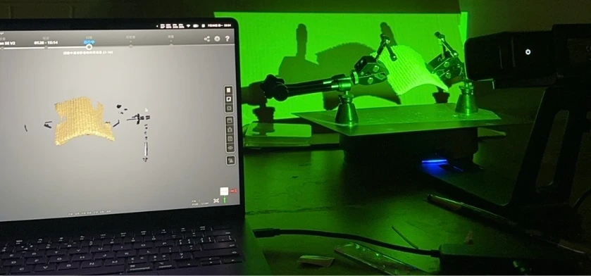
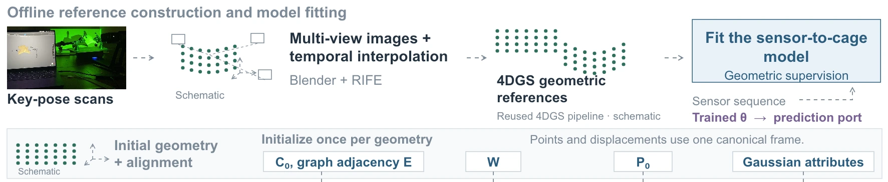
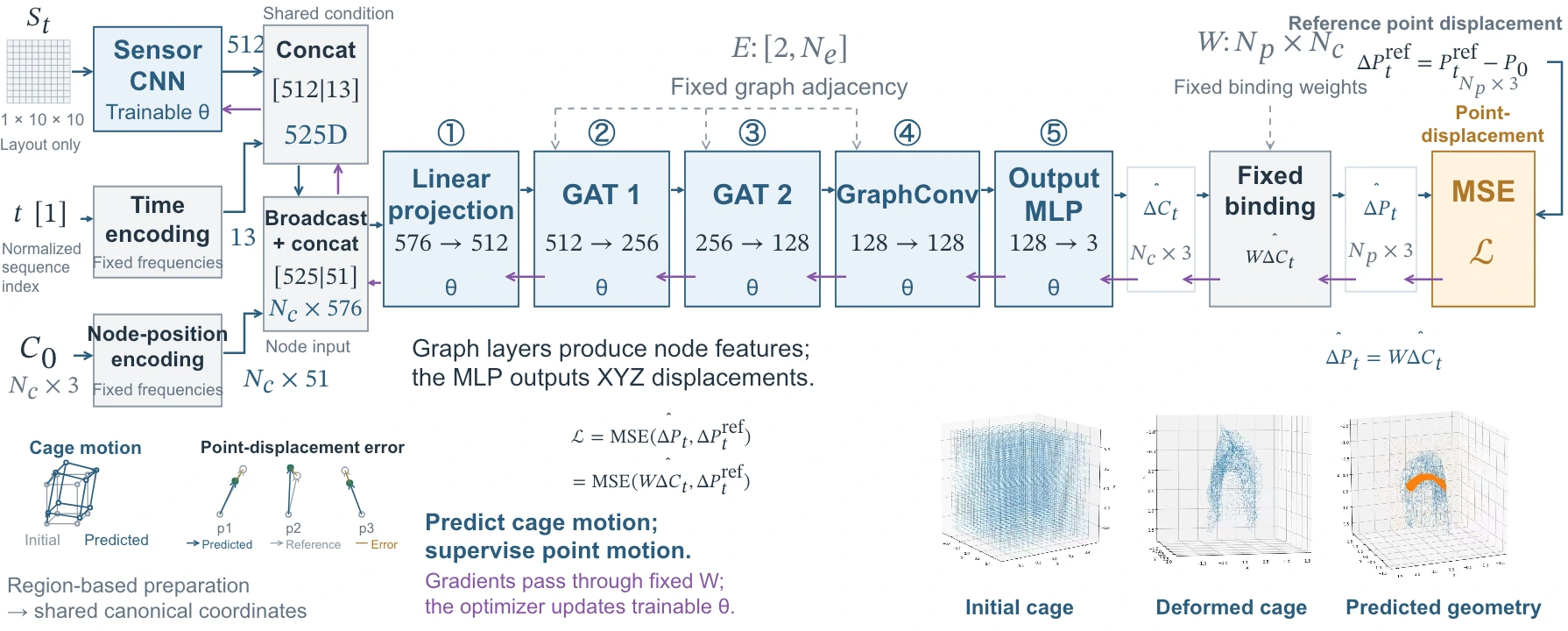
Structured-light scans capture bending and twisting poses. Multi-view rendering, interpolated frames, and 4D Gaussian Splatting provide corresponding geometric motion for supervision. This preparation happens before deployment.
Training the sensor-to-shape model
In the implementation I worked with, the network predicts cage displacement. Fixed weights map it to point displacement; mean-squared error against the reference point motion trains the network by backpropagation.
How this training implementation differs from the paper
The paper describes a separate supervision route: fitting per-frame cage labels by least squares, then training with cage regression and temporal smoothness. The implementation described above instead supervises point displacement after the fixed geometric mapping.
These are different training objectives. The results below are the paper’s reported system results; they are not attributed to a new run of the point-loss implementation.
Reported in the paper
Reconstruction on unseen soft robots
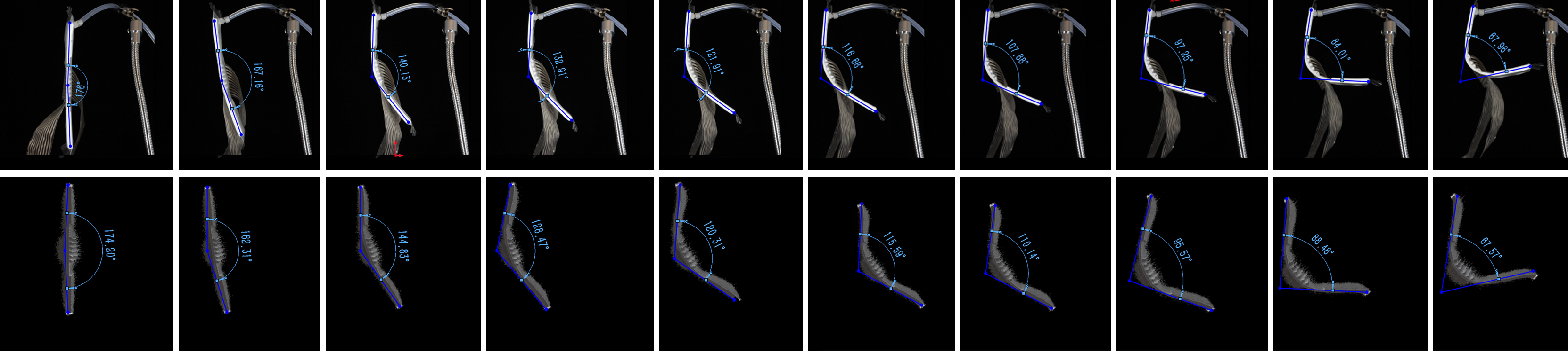
Evaluation covers two soft robots under bending and twisting. The paper also reports IoU of 0.67 ± 0.20, SSIM of 0.65 ± 0.18, and approximately 30 FPS in the coarse setting / 5 FPS at high resolution on an RTX 3070 Ti.
Limitations & next steps
The sensor must follow the surface
The current array bends but has limited stretchability. It struggles to conform to a localized bulge, weakening contact with the object and reducing reconstruction quality. It primarily responds to normal pressure and does not directly measure shear force.
I explored a silicone-based capacitive sensor to improve stretchability and investigate both normal and tangential loading. Fabrication remained challenging. We built an early prototype, but it has not been integrated into the reconstruction system, and reliable shear sensing still needs validation.
A direction I want to pursue: connecting tactile feedback to manipulation policies that can adapt their actions as contact changes.
Read further
Paper & technical details
Zero-Shot Deformation Reconstruction for Soft Robots Using a Flexible Sensor Array and Cage-Based 3D Gaussian Modeling
Linrui Shou, Zilang Chen, Wenjia Xu, Yiyue Luo, and Tingyu Cheng
Accepted to IEEE/RSJ IROS 2026 · June 16, 2026
Full method described in the paper
This section describes the team’s paper method. Its cage-label supervision differs from the point-displacement loss in the training implementation described above.
Creating the Training Supervision
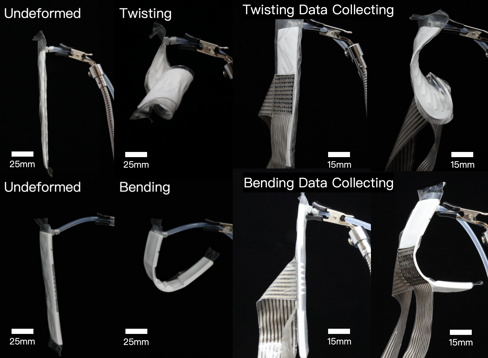
The model was trained on a 10 × 10 cm compliant fabric substrate with a 3 × 3 cm tactile sensor attached to its central region. A mechanical fixture produced repeatable bending and twisting configurations while keeping each selected pose fixed.
For each deformation type, 20 representative poses were captured with a structured light scanner. Each reconstructed shape was then rendered from 100 fixed virtual viewpoints in Blender. The camera parameters remained consistent across poses so that the rendered images shared the same spatial reference.
Because 4D Gaussian Splatting requires a continuous image sequence rather than a small set of isolated poses, RIFE was used to generate 8 to 16 intermediate frames between neighboring poses. This produced approximately 160 time steps for each virtual view and about 16,000 rendered images for each type of motion.
The rendered sequences and camera parameters were then processed with 4DGS. The result was a dense set of Gaussian primitives whose centers remained temporally corresponding as the object changed shape. These Gaussian trajectories provided the geometric supervision used to train the tactile deformation model.
Scanning, Blender rendering, RIFE, and 4DGS were only used to construct the training supervision. They were not required during deployment.
Processing the Tactile Measurements
The tactile patch contained a 10 × 10 grid of electrodes, a Velostat piezoresistive layer, and TPU encapsulation. The electronics scanned the 100 sensing channels and generated one resistance matrix for each sensor frame.
Raw voltage measurements were first converted into resistance values. Each channel was then normalized by dividing its measured resistance R by its resting resistance R0:
\[ R_{\mathrm{normalized}}=\frac{R}{R_0}. \]A low pass IIR filter reduced temporal noise, while a 3 × 3 median filter reduced isolated spatial noise in the resistance matrix.
A lightweight convolutional encoder converted the normalized 10 × 10 matrix into a compact tactile feature. The model also received a six band sinusoidal encoding of normalized time. This encoding indicated the current position within the deformation sequence. It was not a camera signal; it provided temporal context that helped the network distinguish sensor patterns occurring at different stages of bending or twisting.
The tactile feature and temporal encoding were concatenated before being passed to the deformation network.
Representing Deformation with a Control Cage
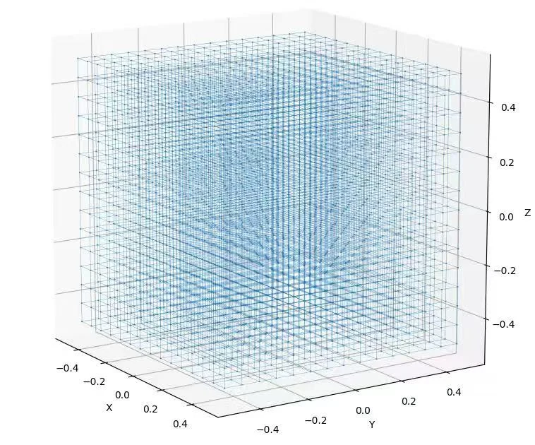
Predicting the displacement of every Gaussian primitive directly would require the network to output hundreds of thousands of motion vectors. The framework instead represented deformation with a regular control cage containing 15 × 15 × 15 nodes, or 3,375 control points.
Each Gaussian center pj was connected to its nearby cage nodes ci. The connection weights were calculated in advance using inverse distance weighting:
\[ w_{ij} = \frac{ \frac{1}{\lVert p_j-c_i\rVert+\varepsilon} }{ \sum_{i' \in \mathcal{N}_k(j)} \frac{1}{\lVert p_j-c_{i'}\rVert+\varepsilon} }. \]A nearby cage node therefore had more influence on a Gaussian than a distant node. The weights were normalized so that the contribution from the neighboring cage nodes summed to one.
This representation reduced the prediction problem from a very large set of Gaussian displacements to a compact and spatially structured set of control point displacements.
Extracting the Cage Training Labels
The 4DGS sequence provided the observed displacement of every Gaussian center at each time step. However, the graph network needed target displacements for the cage nodes rather than for the Gaussians.
Because the relationships between the cage nodes and Gaussian centers were already defined by the inverse distance weights, the system recovered the corresponding cage motion by solving a least squares problem for every training frame:
\[ \min_{\{\Delta c_i\}} \sum_j \left\| \Delta p_j^{\mathrm{gt}} - \sum_i w_{ij}\Delta c_i \right\|_2^2. \]Here, Δpjgt is the Gaussian displacement obtained from 4DGS, while Δci is the unknown displacement of a cage node. The solution produced the cage motion that best reproduced the dense Gaussian deformation. These cage displacements became the target labels used to train the tactile model.
This step connects the image based 4DGS supervision to the sensor based deformation network.
Predicting Cage Motion with Graph Attention
The deformation cage was represented as a graph. Each node corresponded to a cage control point and was connected to its six spatial neighbors.
The combined tactile and temporal feature was passed to a graph attention network. The network contained two GAT layers with four attention heads and 256 hidden units, followed by a GraphConv layer and an MLP. Its final output was a three dimensional displacement vector for every cage node.
Graph attention allowed each node to combine information from its neighbors while assigning different importance to different spatial relationships. This encouraged neighboring parts of the cage to move coherently while still allowing bending and twisting to produce different deformation patterns.
The cage therefore served two purposes. It reduced the size of the network output, and it introduced a spatial structure that discouraged disconnected or irregular motion outside the area directly covered by the sensor.
Training Objective
The network was trained with a cage regression term and a temporal smoothness term:
\[ \mathcal{L} = \frac{1}{N_c} \sum_i \left\| \Delta c_i^{\mathrm{pred}} - \Delta c_i^{\mathrm{gt}} \right\|_2^2 + \lambda \left\| \Delta c_i^{\mathrm{pred}}(t) - \Delta c_i^{\mathrm{pred}}(t-1) \right\|_2^2. \]The first term trained the network to reproduce the cage motion obtained from the 4DGS supervision. The second term penalized sudden changes between neighboring time steps, reducing visible jitter while preserving the underlying motion.
Gaussian noise was added to the sensor input during training to improve robustness to measurement variation. Optional exponential moving average smoothing was also applied during inference to improve temporal stability.
Propagating Cage Motion to the Gaussian Model
During inference, the network predicted the displacement Δci of every cage node. The precomputed inverse distance weights were then used to propagate that motion to each Gaussian center:
\[ \Delta p_j = \sum_{i \in \mathcal{N}_k(j)} w_{ij}\Delta c_i. \]This operation allowed a relatively small number of cage nodes to control a dense Gaussian representation. It also propagated deformation beyond the sensor area while maintaining smooth transitions between neighboring regions.
The system therefore did not attempt to predict every point on the robot independently. It predicted a structured cage motion and used geometry to expand that motion across the complete object.
Rendering the Reconstructed Deformation
After propagation, the system updated the centers of the Gaussian primitives and rendered the resulting deformation with a 3D Gaussian rasterizer.
Only the Gaussian positions were updated at runtime. Their color, opacity, and covariance remained fixed from the representation prepared during training. The renderer therefore did not need to reconstruct the complete visual model for every incoming sensor frame.
This design allowed the system to run at approximately 30 FPS with the coarse Gaussian setting and 5 FPS at high resolution on a single NVIDIA RTX 3070 Ti.
Deployment on Unseen Soft Robots
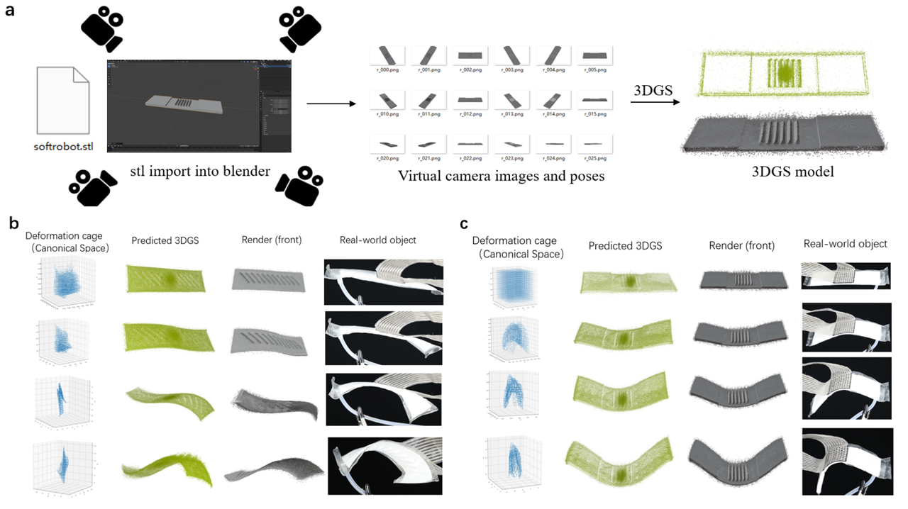
The tactile model was trained only with deformation data collected from the compliant fabric platform. It was later deployed on two soft robots that were not present in the training data. One robot performed pneumatic bending, while the other performed pneumatic twisting.
For each robot, the system began with a static model of its undeformed geometry, such as the STL file used during fabrication. This geometry was converted into a canonical Gaussian representation, and the sensor region was aligned with the corresponding cage region.
The same tactile patch and trained network were then used directly. Each resistance matrix was encoded, the graph network predicted the cage motion, inverse distance weighting updated the Gaussian centers, and the renderer displayed the reconstructed deformation.
No deformation dataset was collected for either test robot. The network was not retrained or fine tuned for their geometry, and no camera image or rendered supervision was supplied during inference. This is the specific meaning of zero shot deployment in this project.
Original method and experiment figures